READING SCHEMATIC
READING SCHEMATIC
Understanding which components are which on a schematic is more than half the battle towards comprehending it. Now all that remains is identifying how all of the symbols are connected together.
NETS, NODES AND LABELS
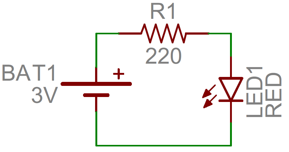
Schematic nets tell you how components are wired together in a circuit. Nets are represented as lines between component terminals. Sometimes (but not always) they’re a unique color, like the green lines in this schematic:
JUNCTION AND NODES
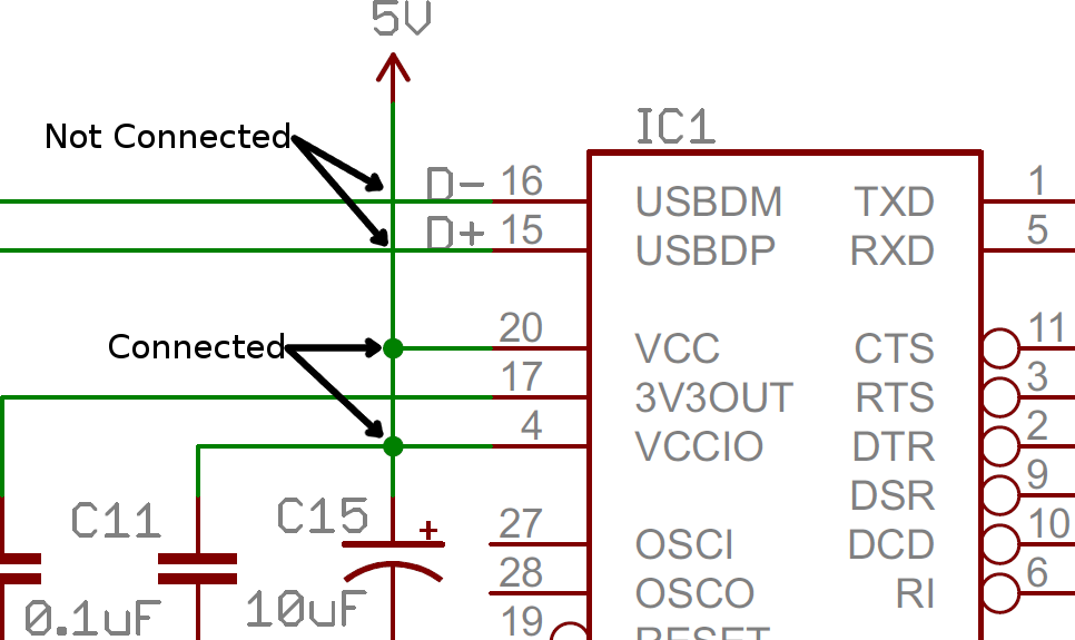
Wires can connect two terminals together, or they can connect dozens. When a wire splits into two directions, it creates a junction. We represent junctions on schematics with nodes, little dots placed at the intersection of the wires.
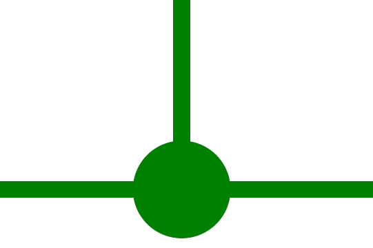
Nodes give us a way to say that “wires crossing this junction are connected”. The absences of a node at a junction means two separate wires are just passing by, not forming any sort of connection. (When designing schematics, it’s usually good practice to avoid these non-connected overlaps wherever possible, but sometimes it’s unavoidable).